Hosseg.com

How Can We Help
If you need any helps, please feel free to contact us.
Call Us

+48 519 821 507

Or mail

contact@hosseg.com

industrial facility, likely a power plant or refinery. It features several large cylindrical towers and chimneys, with extensive piping and metal frameworks. The structures include staircases, platforms, and safety railings, indicating a complex operational environment. There are various industrial components such as ducts, valves, and control units. A yellow waste bin and a fenced area are visible in the foreground, and the sky is overcast with some clouds. The overall setting appears to be an outdoor industrial site with heavy machinery and infrastructure.

Process Efficiency Optimization

At Hosseg, we focus on enhancing industrial process efficiency, offering advanced solutions for software adjustments and hardware modernization. With years of specialist experience, we effectively analyze and improve control and monitoring systems, identifying key areas for enhancement.

Over time, industrial installations such as steam boilers, HRSG systems, flue gas and industrial gas treatment installations, and other process systems undergo natural wear. As a result, control and monitoring precision gradually declines, leading to reduced operational efficiency. Equipment operating parameters change, and software originally tailored to operational conditions becomes outdated. In such cases, system recalibration or modernization of key components becomes necessary—often much faster than commissioning a new installation.

We specialize in the following areas:

  • HRSG and Steam Boilers – optimizing heat recovery and steam production systems.
  • Flue Gas Treatment Installations – improving treatment process efficiency.
  • Process Equipment and Installations – enhancing reliability and performance.
  • Pipelines – modernizing and adapting to new operating conditions.
  • Flow Control – precise media flow management.
  • Bulk Material Handling – streamlining transport and storage processes.

Our service is based on a comprehensive approach: we conduct detailed analyses, tests, and calculations to determine which elements—software or hardware—require optimization. We offer updates and enhancements to control and measurement systems, as well as replacement, modernization, or adjustment of installation components. This increases the efficiency, performance, and reliability of industrial systems, reducing failure risks and ensuring stable operation.

Hosseg is a partner that not only restores full installation functionality but also adapts it to current requirements, extending its lifespan and maximizing operational potential. Our expertise and specialization enable us to deliver tailored solutions, supporting clients in maintaining a competitive edge in demanding industrial environments.

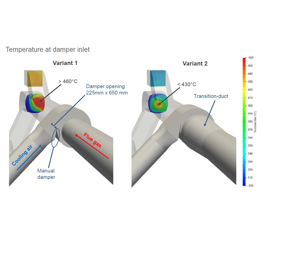
CFD Analysis of Flue Gas Ducting
computational fluid dynamics (CFD) simulation, illustrating the velocity field of a fluid flow. It shows a cross-section of a channel or vessel with streamlines indicating the direction and speed of the flow. The color gradient, ranging from blue (0 m/s) to red (40 m/s), represents the velocity magnitude, with blue indicating slower speeds and red indicating higher speeds. The flow appears to have complex patterns, including swirls and variations in velocity, suggesting turbulence or specific flow conditions within the structure. A color scale on the right provides a reference for the velocity values.
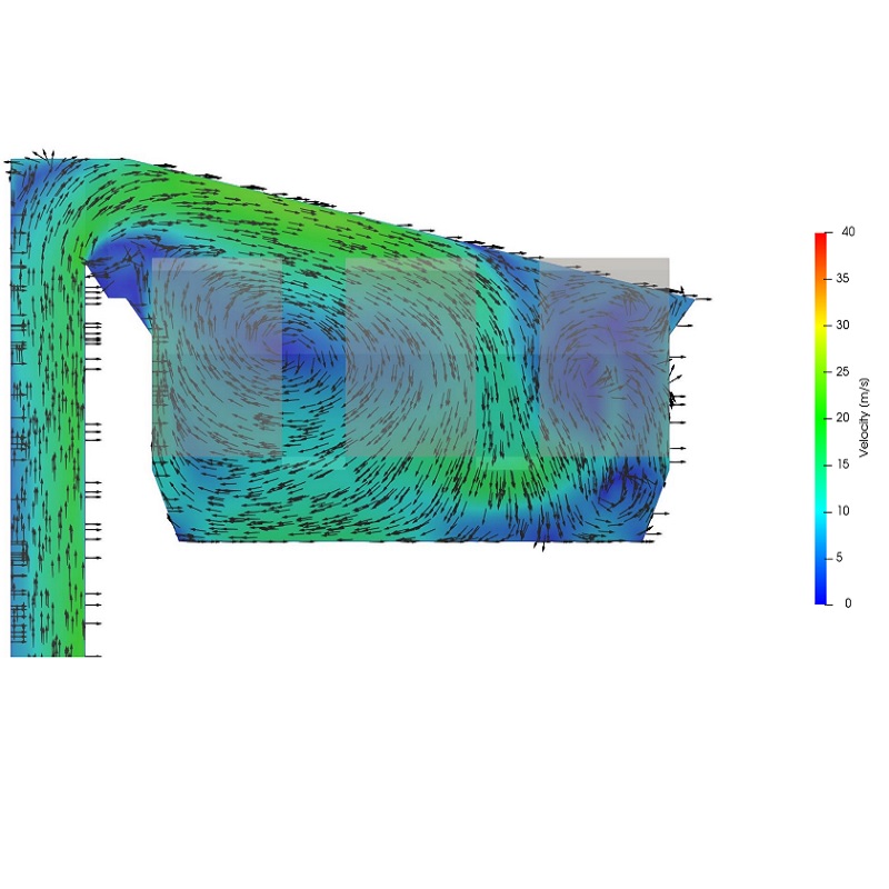
Determination of pressure drop in the flue gas duct
computer monitor displaying a software interface, likely used for industrial or scientific purposes. The screen features a control panel on the left with various parameters and readings, including flow rates (e.g., 0.27703 and 0.0300 m³/h), pressure values (e.g., 16.10 kPa and 17.23 kPa), and other metrics like temperature (34.88°C). The interface includes buttons like "START," "STOP," and "GRAFIKON" (likely "Graph" in a different language). On the right side, there is a graph or visualization area with a grid, displaying a few data points or a small plot, possibly representing real-time data from a pump or flow system. The monitor is a Dell model, and the setup appears to be in a technical or laboratory environment, with a diagram or equipment illustration visible in the background.
CFD simulation of air injection
Two variants of a duct system used for handling hot flue gases. Variant 1 features a manual damper with an opening size of 225 mm x 650 mm. Cooling air is introduced through a separate duct to cool the system. The temperature at the critical point exceeds 460°C, as shown by the red area in the thermal simulation. Variant 2 replaces the manual damper with a transition duct. In this design, the temperature is reduced to below 430°C, indicated by the green and yellow zones in the thermal image. This suggests better thermal performance and lower peak temperatures. A temperature scale from 300°C to 460°C is displayed on the right for reference.
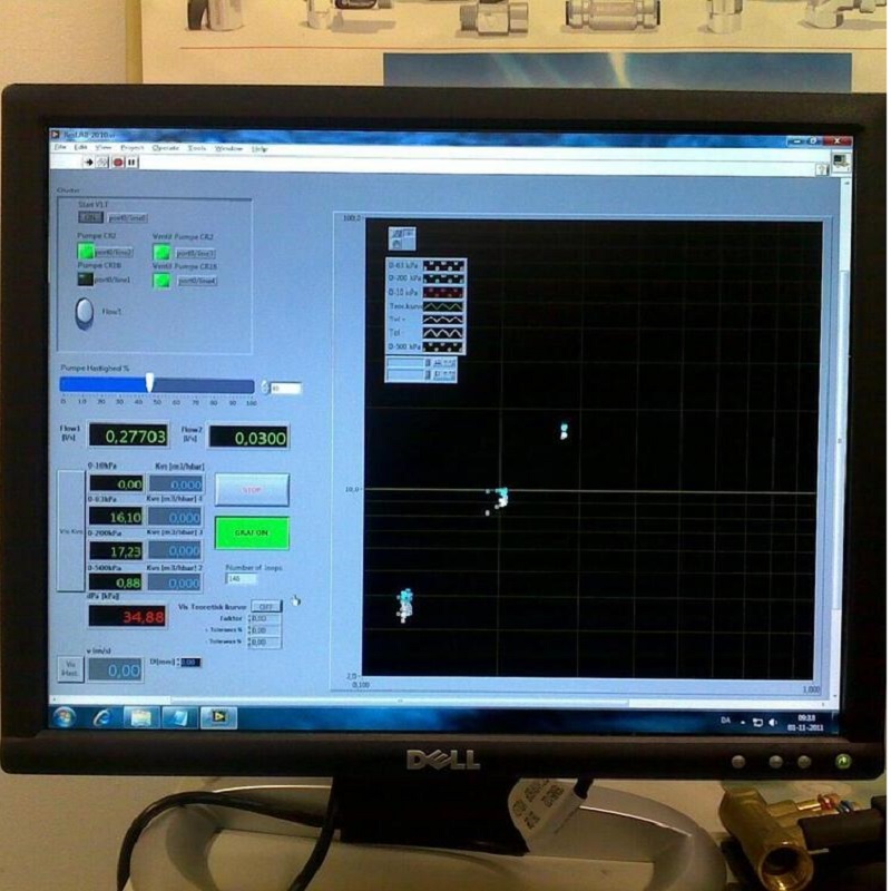
Determination of the Kv coefficient of the orifice